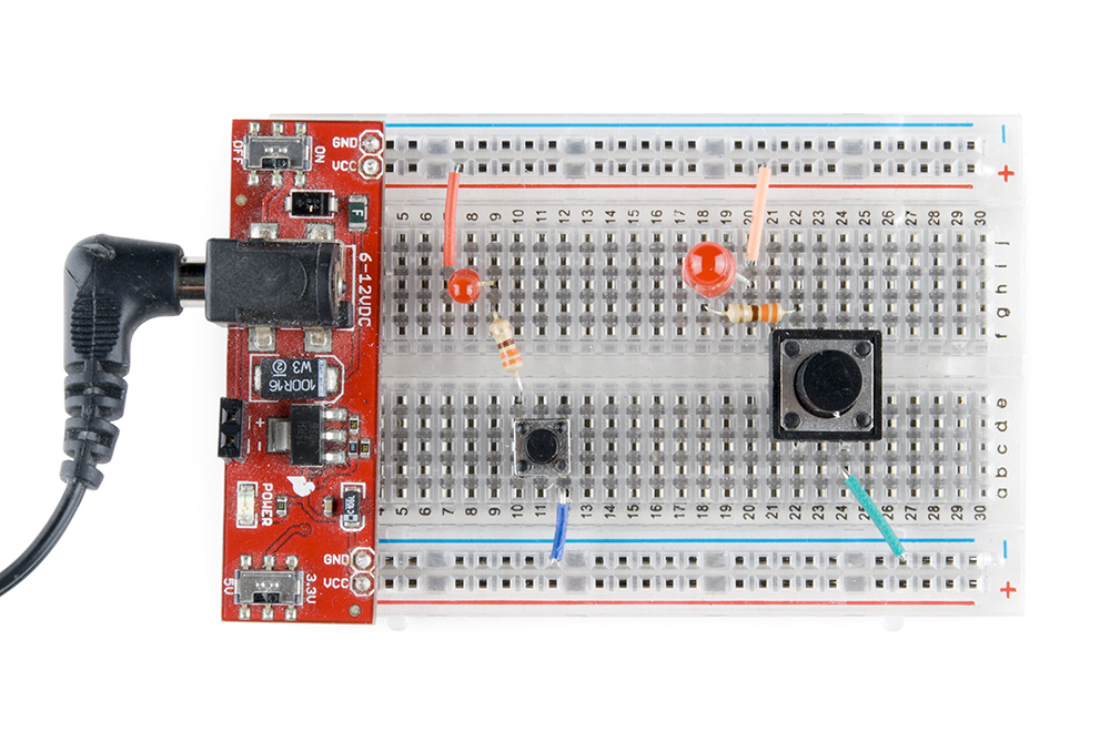
A breadboard diagram is a computer generated drawing of a circuit on a breadboard. This is standard because when you start using larger chips like integrated circuits the dip packages fit right into the breadboards.
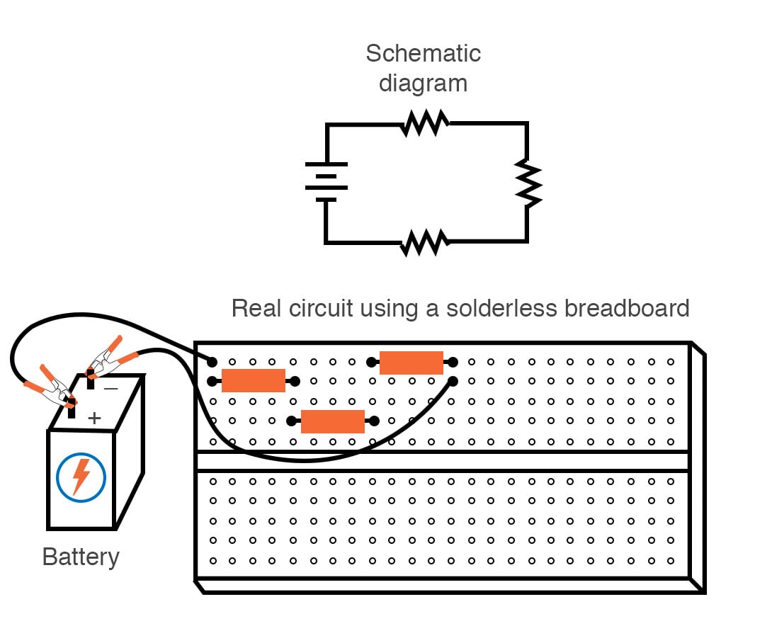
For our first circuit we will be using resistor networks.

How to use a breadboard to make a circuit.
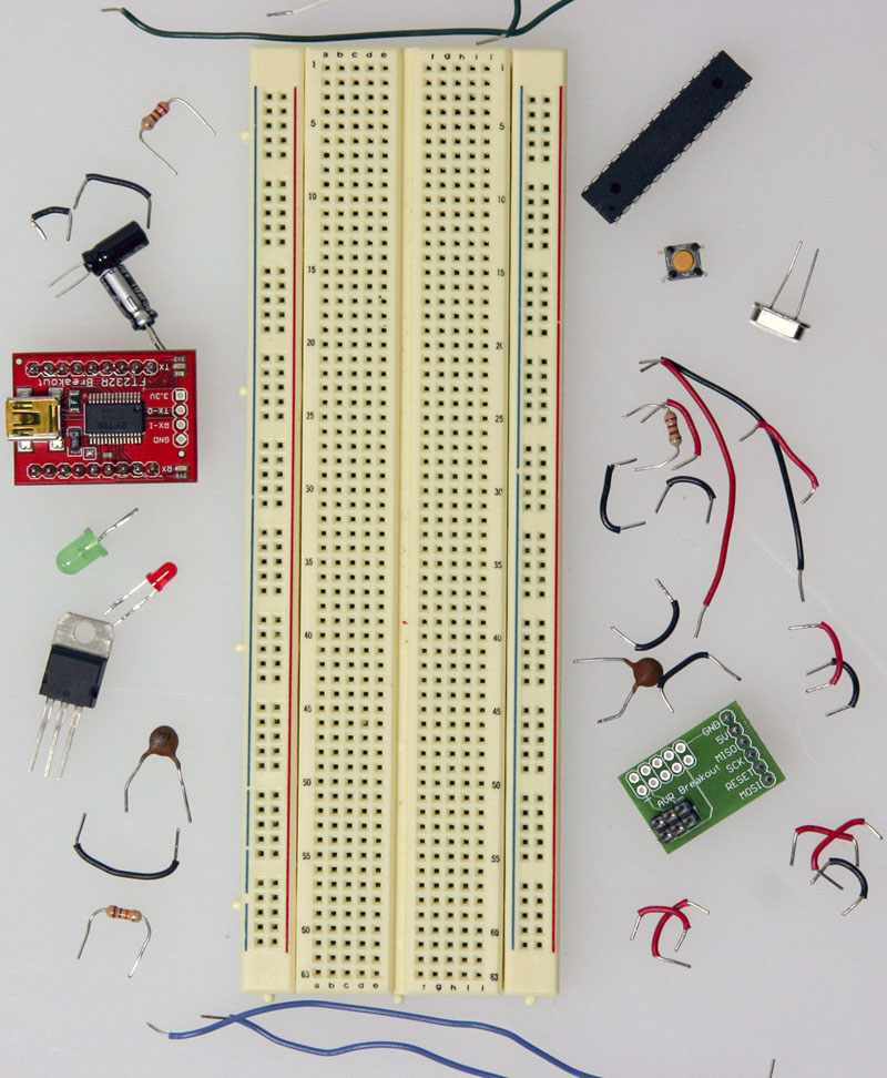
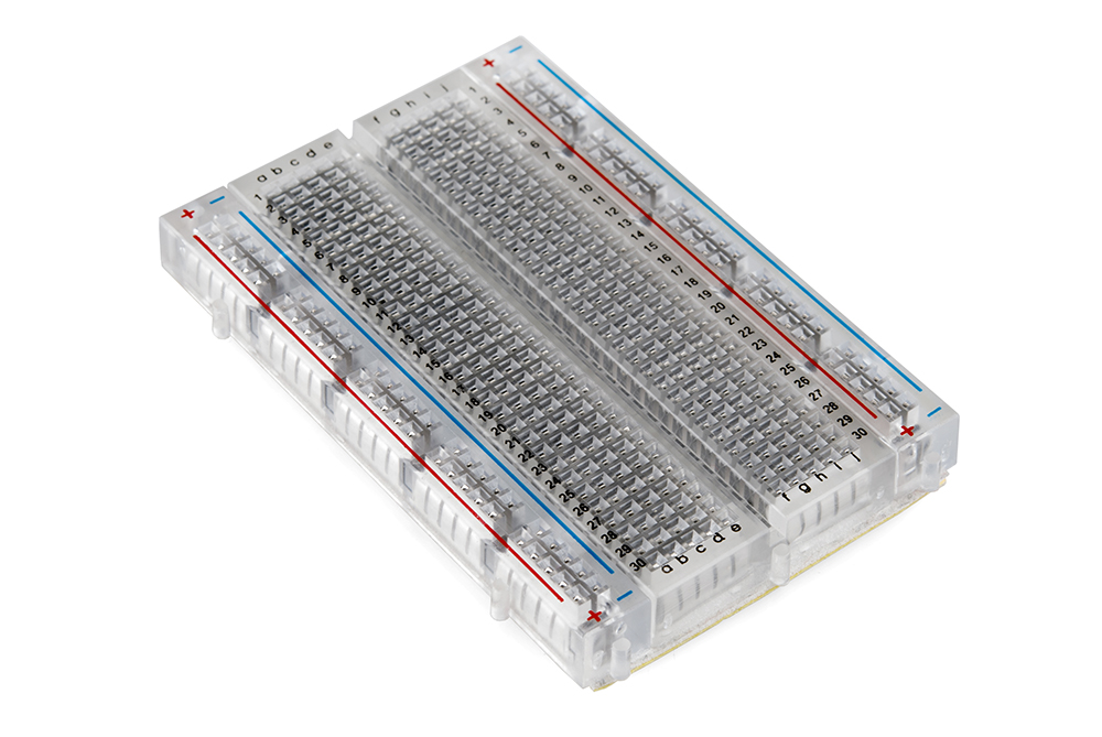
Breadboards use letter for columns and number for rows to specify a hole.
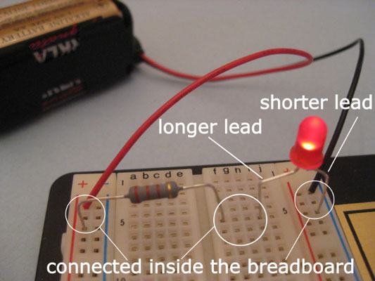
When you use a breadboard to build a circuit you insert the parts directly into those holes.
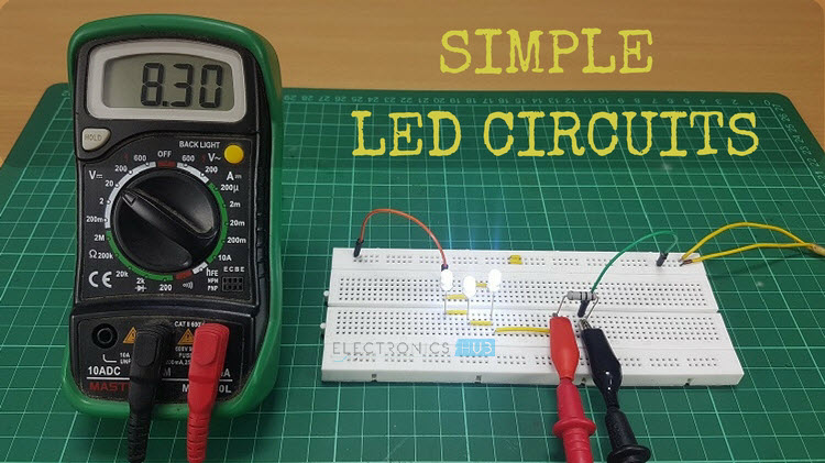
This tutorial shows you how to use a solderless breadboard to build an electronic circuit including the basics of how a breadboard works and some common mistakes that beginners make.
You can find.
Take r1 and put one lead in a5 and another lead in a15 take r2 and put its leads to b15 and b25.
The typical breadboard is laid out in a matrix of 1 inch spaced holes.
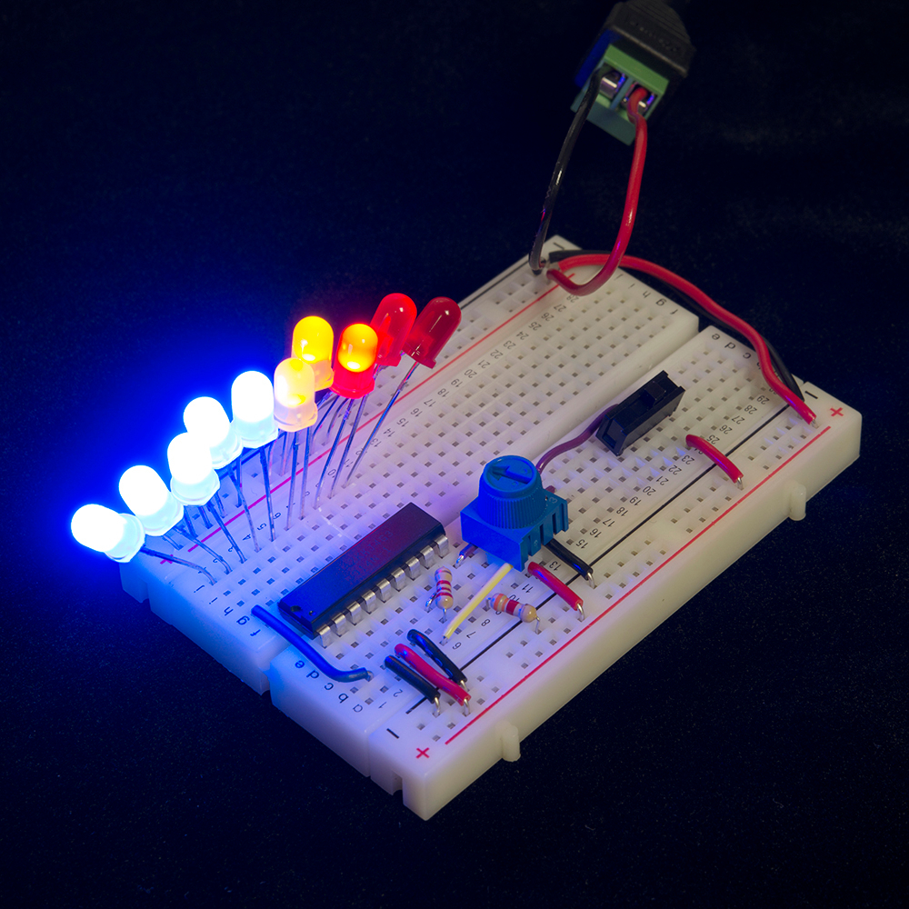
See the advanced section to learn more breadboard diagrams make it easy for beginners to follow instructions to build a circuit because they are designed to look like the real thing.
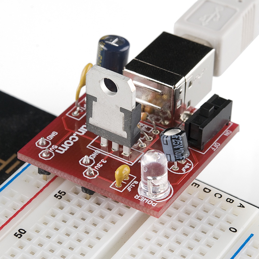
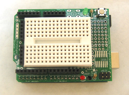
Also many headers and breadboard friendly components will fit nicely.
Each of the short rows of 5 holes are connected.
Most through hole integrated circuit chips or ics will fit snuggly in this matrix.
Unlike a circuit diagram or a schematic which use symbols to represent electronic components.
Some of these holes are electrically connected to others inside the breadboard.
You can easily see which holes are electrically connected.
Things we will need.
Which holes you plug them into does matter.
1breadboard 2resistors 4x100ohm brownblackbrown r1r2r3r4 3multimeter step 1.
You can specify a hole using the row number and column letter.








No comments:
Post a Comment